the
Thin Wall Bolt
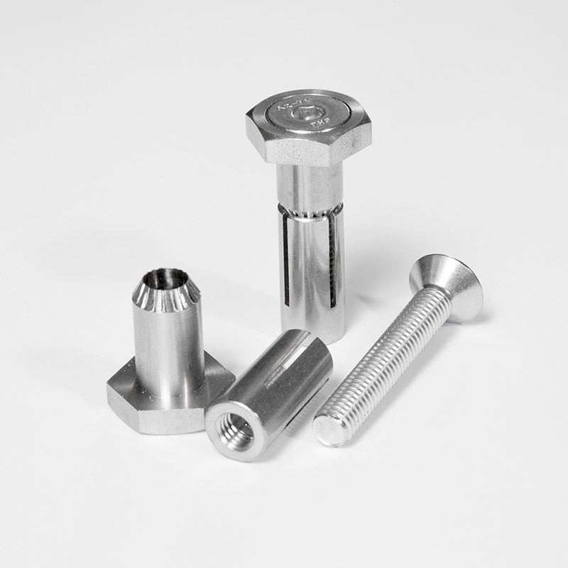
Our thin wall bolt (also known as a TW Bolt), when used correctly, offers a combination of a high shear capacity and inherent strength.
Thin Wall Fasteners
TW Bolt was designed by us to deal with the problems faced when putting lightweight steel sheet or cladding material in place using a blind fixing. Once the material in question has been installed, all that will be visible will be a low profile head with no stud. Other positive aspects of our thin wall bolts are as follows:
- Overall assembly takes less time thanks to easy and swift installation
- The hole required doesn’t have to be drilled any larger than the norm
- Durability and longevity ensured by the zinc electroplate finish
If you want to stay on top of all of our exciting new products and developments, please visit our news page, or contact us using the details below. Outline your project to us, and we’ll explain how blind bolt fasteners could make a difference.
Thin Wall Bolt
Technical Data
NOTE: All dimensions are in mm unless stated otherwise.
The Blind Bolt Company reserve the right to change these technical details without notice.
Thin Wall Bolt Product Specification - Zinc Nickel |
||||
| PRODUCT CODE |
HOLE DIAMETER |
DEPTH CLEARANCE |
CLAMPING RANGE |
|
| (mm) | (mm) | MIN (mm) | MAX (mm) | |
| TW5ZF-10 | 8 | 35 | 2 | 10 |
| TW5ZF-16 | 8 | 40 | 8 | 16 |
| TW6ZF-10 | 10 | 35 | 2 | 10 |
| TW6ZF-16 | 10 | 40 | 8 | 16 |
| TW8ZF-10 | 13 | 45 | 2 | 10 |
| TW8ZF-16 | 13 | 50 | 8 | 16 |
Design Resistance for TW Type Blind Bolts Design to BS 5950 - Zinc Nickel |
|||||
| TW Bolt Size |
Set Screw Diameter (mm) |
Collar Outside Diameter (mm) |
Hole Diameter (mm) |
Shear Resistance (kN) |
Tension Resistance (kN) |
| TW5 | 5 | 7.8 | 8 | 13.2 | 4.8 |
| TW6 | 6 | 9.5 | 10 | 19.5 | 14.1 |
| TW8 | 8 | 12.6 | 13 | 34.5 | 25.6 |
Design resistances in shear and tension are presented above. The resistance values may be compared directly with the ultimate loads applied to the fixing.
The bearing resistance may be calculated in accordance with the design standard, based on the external diameter of the collar, as given above.
Fixings subject to combined shear and tension should be verified in accordance with the design standard, using the design resistances presented above.
If tension is applied to a fixing in a relatively thin wall application, the deformation of the connected material should be considered at serviceability (working loads) and at the ultimate limit state, as deformation is likely to be the limiting feature of the connection.
Design Resistance for TW Type Blind Bolts Design to BS EN 1993 - Zinc Nickel |
|||||
| TW Bolt Size |
Set Screw Diameter (mm) |
Collar Outside Diameter (mm) |
Hole Diameter (mm) |
Shear Resistance (kN) |
Tension Resistance (kN) |
| TW5 | 5 | 7.8 | 8 | 15.9 | 4.8 |
| TW6 | 6 | 9.5 | 10 | 23.4 | 10.1 |
| TW8 | 8 | 12.6 | 13 | 41.4 | 18.4 |
Design resistances in shear and tension are presented above. The resistance values may be compared directly with the ultimate loads applied to the fixing.
The bearing resistance may be calculated in accordance with the design standard, based on the external diameter of the collar, as given above.
Fixings subject to combined shear and tension should be verified in accordance with the design standard, using the design resistances presented above.
If tension is applied to a fixing in a relatively thin wall application, the deformation of the connected material should be considered at serviceability (working loads) and at the ultimate limit state, as deformation is likely to be the limiting feature of the connection.
Stainless Steel Thin Wall Bolts
Thin Wall Bolt Product Specification Stainless Steel A2-70 |
||||
| PRODUCT CODE |
HOLE DIAMETER |
DEPTH CLEARANCE |
CLAMPING RANGE |
|
| (mm) | (mm) | MIN (mm) | MAX (mm) | |
| TW5SS-10 | 8 | 35 | 2 | 10 |
| TW5SS-16 | 8 | 40 | 8 | 16 |
| TW6SS-10 | 10 | 35 | 2 | 10 |
| TW6SS-16 | 10 | 40 | 8 | 16 |
| TW8SS-10 | 13 | 45 | 2 | 10 |
| TW8SS-16 | 13 | 50 | 8 | 16 |
Design Resistance for TW Type Blind Bolts Design to BS 5950 - Stainless Steel A2-70 |
|||||
| TW Bolt Size |
Set Screw Diameter (mm) |
Collar Outside Diameter (mm) |
Hole Diameter (mm) |
Shear Resistance (kN) |
Tension Resistance (kN) |
| TW5 | 5 | 7.8 | 8 | 11.6 | 7.0 |
| TW6 | 6 | 9.5 | 10 | 17.3 | 9.8 |
| TW8 | 8 | 12.6 | 13 | 30.4 | 17.9 |
Design resistances in shear and tension are presented above. The resistance values may be compared directly with the ultimate loads applied to the fixing.
The bearing resistance may be calculated in accordance with the design standard, based on the external diameter of the collar, as given above.
Fixings subject to combined shear and tension should be verified in accordance with the design standard, using the design resistances presented above.
If tension is applied to a fixing in a relatively thin wall application, the deformation of the connected material should be considered at serviceability (working loads) and at the ultimate limit state, as deformation is likely to be the limiting feature of the connection.
Design Resistance for TW Type Blind Bolts Design to BS En 1993 -
|
|||||
| TW Bolt Size |
Set Screw Diameter (mm) |
Collar Outside Diameter (mm) |
Hole Diameter (mm) |
Shear Resistance (kN) |
Tension Resistance (kN) |
| TW5 | 5 | 7.8 | 8 | 14.0 | 5.0 |
| TW6 | 6 | 9.5 | 10 | 20.8 | 7.1 |
| TW8 | 8 | 12.6 | 13 | 36.4 | 12.9 |
Design resistances in shear and tension are presented above. The resistance values may be compared directly with the ultimate loads applied to the fixing.
The bearing resistance may be calculated in accordance with the design standard, based on the external diameter of the collar, as given above.
Fixings subject to combined shear and tension should be verified in accordance with the design standard, using the design resistances presented above.
If tension is applied to a fixing in a relatively thin wall application, the deformation of the connected material should be considered at serviceability (working loads) and at the ultimate limit state, as deformation is likely to be the limiting feature of the connection.
Thin Wall Bolt
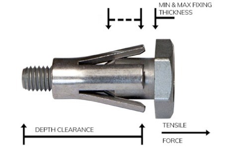
Testing Terms Explained
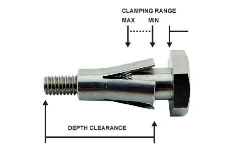
The unique and innovative nature of the thin wall bolt helps to make it flexible and convenient, but it also dictates that particular criteria have to be in place if the bolts in question are to function properly. The meaning of the various measurements applied to the bolt, and the application of these figures, has to be understood.
The above illustration conveys these measurements, and the menu below offers individual explanations. If you’d like to know more, or ask exactly how you can use thin wall bolts, please get in touch using the number below or email us here.
Thin Wall Bolt
Fitting Instructions
Installations & Removal Videos
The following videos visually represents the detailed installation of the Thin Wall Bolt.

Thin Wall Bolt
SCI Report
