
solution
find the right Blind Bolt
The smart
solution
for steelwork connections
Find
your
Standard
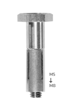
Blindbolt
Input The Total Thickness
(Total Clamping Thickness)

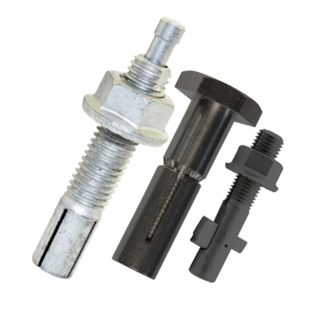
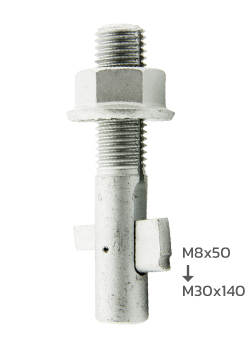
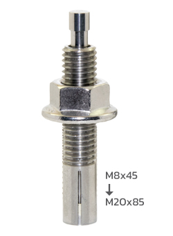
The Standard
Blindbolt
Flexible, high speed
blind fixing for multiple
applications
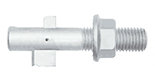
The Heavy Duty
Blindbolt
For heavy-duty anti-shear
applications available in
multiple finishes
The Thin Wall
Blindbolt
For fixing light weight
materials, such as sheet
steel / cladding
Save time,
Save money,
Fix it with a Blind Bolt
How does it work?
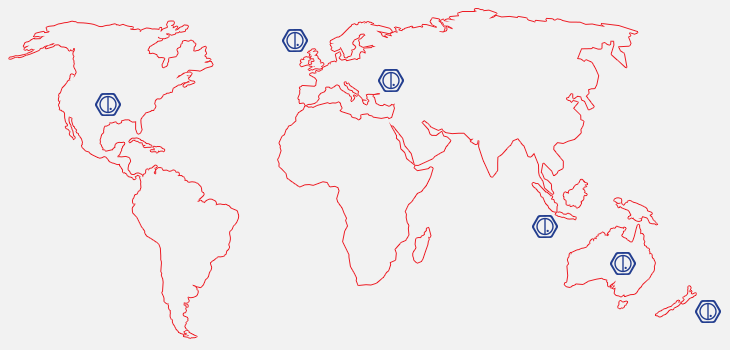
Global
Distributor
Network
The BlindBolt fixings solutions range is available from a network of dedicated worldwide distributors...
And as an ever expanding organisation we welcome the opportunity to work alongside organisations that will help our growing worldwide client base.
Contact
Got a question?
Get in touch by using our contact for, sending an email, or calling us on:
+603-33775597